This paper proposes an analytical approach for modeling low frequency Differential Model (DM) Electromagnetic Interference (EMI) noise of single-phase Power Factor Correction (PFC) converters
Developing an electrical BESS architecture outlining the system components and their interconnections. Creating a single-line diagram (SLD) of the BESS system for clear visualization of power flow. Preparing a layout of the BESS plant,

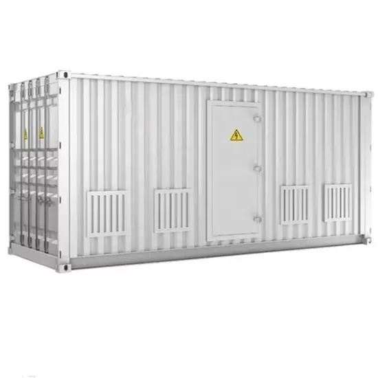
025 2 MW BESS architecture of a single module 026– 033 Remote monitoring system. 4 UTILITY SCALE BATTERY ENERGY STORAGE SYSTEM (BESS) BESS DESIGN IEC - 4.0 MWH SYSTEM DESIGN Single-line diagram design. Battery rack1 MV utility MV/LV transformer Power conversion system (PCS) DC combiner Battery rack Battery rack Battery rack Battery rack
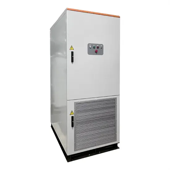
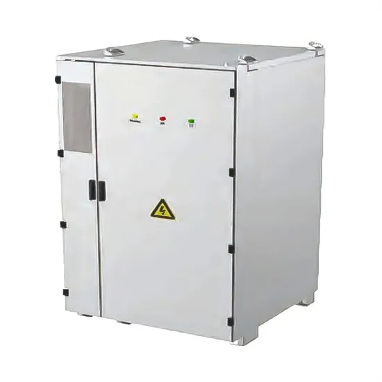
Simplified single-line diagram for BESS. Figure 2. 2 MW BESS Power Conversion System enclosure. Technical Datasheet | 2 MW PCS Unit for BESS Applications 3 Primary Switchgear Since the PCS in most cases is connected directly to a utility line, it is necessary to have some disconnect means and
The single-line diagram is the blueprint for electrical system analysis. It is the first step in preparing a critical response plan, allowing you to become thoroughly familiar with the electrical distribution system layout and design in your facility.
The fundamental course is to expose participants to the development of layouts and single line diagrams of major power systems including renewable inverters, transformers, collector system, Gen-tie for PV, and BESS Renewable Energy systems. In addition to this, Individual equipment data and SLD modification based on the specific project
A single line diagram is a simplified schematic of a multi-line power distribution system, which may include three-phase, three-phase with neutral, single-phase with neutral, or direct current with two lines. One-line diagrams utilize a single line to represent the many components of a distribution system as seen in a schematic or wiring diagram.
Need help integrating a BESS into your current renewable infrastructure? Electrical Reliability Services'' NETA certified technicians, engineers, and project managers are well-versed on the components that make up your Battery Energy Storage System (BESS). Overview Arc Flash Studies Single-Line Diagrams Protection & Controls. Overview
Single-Line Review and Update. In many facilities, loads are continually added or removed in small increments. The net effect is not always seen until some part of the system becomes overloaded or exhibits other problems. Following a site survey, ERS engineers will update existing single-line diagrams or complete electrical system drawings as
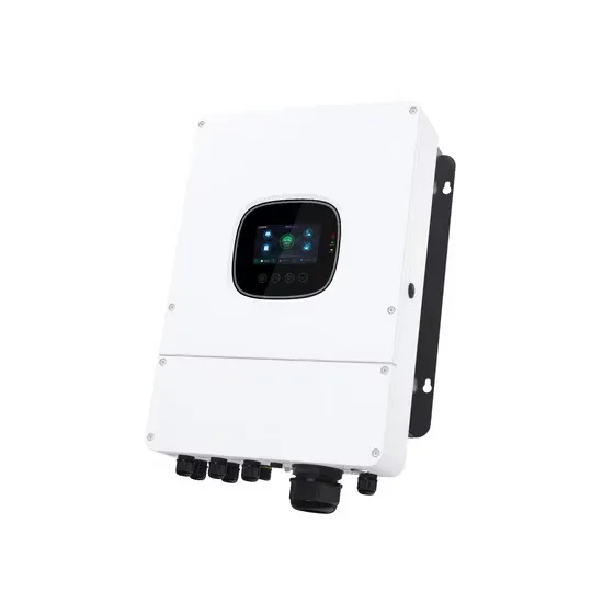
Figure 3 shows a typical single line diagram of an integrated solution. A BESS can perform the following applications to facilitate the integration of these renewable generation resources into
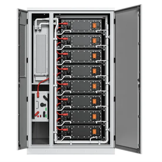
The minimum unit or block of the BESS is the set of a PCS and the containers connected to it. Power Conversion System (PCS): Alternatively, you can set the capacity of a single battery rack and the number of racks to include per container. RatedPower will install the necessary number of containers according to the system requirements.
The single-line diagram provides the roadmap to enable proper design of equipment, redundancy, and protection. NFPA-70E requirements mandate accurate, up-to-date single-line diagrams. To meet these requirements, Vertiv can conduct a comprehensive site survey to develop single-line diagrams for your facility or to update existing diagrams.
However, because the capacity of BESS is calculated under balanced conditions, the PCS (Power conversion system) of BESS may stop protecting its switching device from a single phase overcurrent in
2. Interpreting a LV Panel Single-Line Diagram. A single-line diagram (SLD) or a one-line diagram (OLD) is a simplified schematic representing a three-phase system''s electrical elements with a single line representing the connected conductors. We can say that the single-line diagram is finished once all loads are distributed throughout the
The single-line diagram is the blueprint for electrical system analysis. It is the first step in preparing a critical response plan, allowing you to become thoroughly familiar with the electrical distribution system layout and design in your facility.
This PV generation may also be able to charge the BESS if for some reason there was a shortage of cheaper energy in off peak times necessary to charge the BESS fully for its next load leveling operation. The single line diagram of the system used during this project is shown in Figure 2 below. Figure 2. System Single Line Diagram
Figure 2b – Power System Single Line Diagram (Continued) Go back to Content Table ↑. 3. Standardized Drawing Symbols 3.1 General. In the North American market, the American National Standards Institute (or ANSI for short), in cooperation with the Institute of Electrical & Electronics Engineers has developed standardized drawing symbols and
Option to select a more optimised voltage ratio between grid and BESS AC output. This may allow for lower DC link operating voltages than a direct connection. Figure 1 – Single-line diagram of a BESS comprised of two
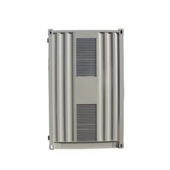
Figure 2b – Power System Single Line Diagram (Continued) Go back to Content Table ↑. 3. Standardized Drawing Symbols 3.1 General. In the North American market, the American National Standards Institute (or ANSI
BESS Design and Engineering These are the FEED and detailed design considerations that must be made when deciding on how best to integrate BESS into a design. The grid connection point should be decided early in the design phase. It may be decided to split the BESS into two or more distinct units for connection at multiple points in the network.
It may be decided to split the BESS into two or more distinct units for connection at multiple points in the network. This can be done to allow multiple sections to function independently with BESS support, as well as provide redundancy in system design. The type of connection should be decided early.
When connecting to an LV network, the BESS can be treated similar to a generator incomer, though energy flow will be bi-directional. Depending on the AC drive configuration, it may be possible to connect the BESS directly to the network before the output is modulating, and have the drive perform a ‘ flying synchronisation ’.
If the BESS shall connect to a LV or MV connection point. Most battery systems will not exceed 1500 V DC, as this would bring them into the HV classification range and entail increased equipment and operational demands. Additionally, it may be difficult to find DC switchgear rated to such high voltages and current.
The type of connection should be decided early. If the BESS shall connect to a LV or MV connection point. Most battery systems will not exceed 1500 V DC, as this would bring them into the HV classification range and entail increased equipment and operational demands.
The BESS can perform load following, where the generation will follow the demand up or down instead of making a baseload plant cycle, thus decreasing emissions and increasing efficiency of the system. Individual components, such as integrated solutions with connection equipment (inverter, AC/DC protection, trans-former, enclosure).