Each terminal in the series has a connection to the battery and a crimp to the cable for the battery before it (2 connections) and another set of two for the battery after it. With bus bars, there is only a connection to the battery (1/4 the number of connections).
If connecting to a bus bar, you typically use a ring terminal at the bus bar, and many MPPT have some sort of "pinch" terminal that works on bare wire. Size wire based on anticipated current. Fuse/breaker for 1.25X wire rating. e.g., a 30A MPPT can use 10awg from MPPT to bus bar with a 40A breaker or fuse.
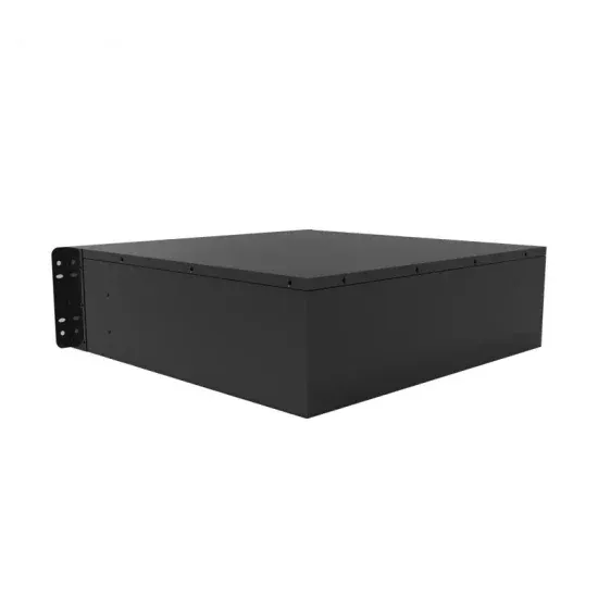
Battery bank connections: Busbars can be used to interconnect the various batteries in your battery bank. This allows for a central point of connection, reducing the complexity of wiring and ensuring that all batteries receive an equal charge and discharge, like in Lithium battery connections where they must be connected in parallel.
Hybrid Inverter & Battery Bundles - No Solar (ESS) Grid Inverter & Solar Bundles - No Storage Use these to connect your battery banks so that the load is spread better and your batteries will last longer. Solid copper bus bar. 9 ways. Manufactured from 25mm x 6mm high grade C101 solid copper bar. All connections are M8. Total bar length
I have two arrays. Each array has six panels. The panels are wired as 2S3P on each array. Currently I have each array connected to it''s own Epever Tracer 4210an. Each MPPT feedings it''s own battery bank. Bank #1 is 24v Flooded 660amp. Bank#2 24v Lifepo4 400amp. Is it possible to tie in all...
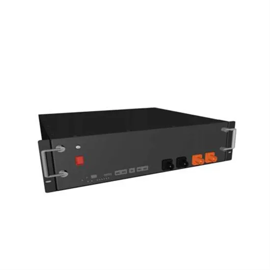
A terminal block, or battery busbar, is a specific type used in battery systems, including those in solar power installations. It serves a similar function as a regular busbar, but it is specifically designed to connect multiple
busbar length charge/discharge battery bank balance. Thread starter ben22; Start date Jul 8, 2022; B. ben22 New Member. Joined Jun 11, 2022 should i use 2 x 1p breakers one between battery and inverter positive and one between battery and solar controller positive or can i use one 2p breakers one leg to inverter and one leg to solar
Connecting more than one charge controller to the same battery bank ? Examples (some or all at once, even multiples of a single type, different brands, etc.): Solar PV via MPPT Solar PV via PWM AC-DC... diysolarforum Reactions: Whats-n-Watts. Chadd New Member. Joined Jul 13, 2022 Messages 101. Sep 12, 2022 #3
So, I plan to use a positive and negative busbar that will allow me to combine the outputs of the batteries and ensure that each battery''s pos. I''ve been looking at BMS-controlled LiFePO4 batteries to replace my AGM battery bank when the
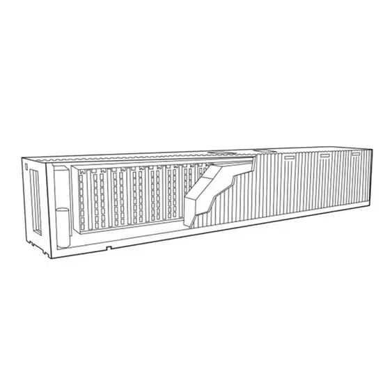
Re: Busbar as Battery Interconnects I have run into many inustrial battery banks used in power plants to supply emergency turbine lube oil cooling and other emergency loads with bus bars between the batteries. These battery rooms are quite impressive with numerous very large batteries hooked in series. My former employer also used bus extensively in off grid batter banks.
Our battery racks for these actually have bus bars on the side that you connect to with a short cable. That would be my recommendation - that is, get a bus bar and connect to it with short cables off-set from the battery. You don''t need the battery rack itself - just the idea of the bus bar with the short cables.
Hi, pretty new to solar and I''ve been crash coursing myself for the past couple days. Currently doing a bus build and saw the price of battleborns which 180''d me to look at diy options. After browsing for a bit I found a good deal on prepackaged cells from Batteryhookup (...

My Battery to Bus Bar runs are 5'' / 1.524m long, from BusBar to DC E-Panel then to Inverter is another 8''. So I sized to negate any derration and to be able to handle 300A comfortably. Observed during operation: The four battery packs in the LFP bank (2x 280AH & 2x 174AH) do share load & charge quite evenly. The smaller capacity packs will
The busbars can be sized to the max load on the system. With two parallel banks, that is a total of 200A and at the lower end of the battery voltage that works out to 48 * 200 = 9600W at the higher end of the battery voltage that is 57.6 x 200 = 11,520W. What is the max wattage you expect on your system?

2 Battery Banks on 1 solar system - Looking for some kind of Switch to go from main bank to a reserve bank Echo; Jul 9, 2024; DIY Solar General Discussion; Replies 12 DIY bus bars for 2p8s battery bank Kraken; Apr 3, 2024; Beginners Corner and Safety Check; Replies 5 Views 674. May 14, 2024. littleharbor2. L. Share:
As technology continues to evolve within the solar industry, many companies are now enhancing their panels with higher busbar counts compared to just a year ago. For anyone unfamiliar with the term busbar, a busbar, often made from aluminum or copper, is a thin strip of metal that conducts electricity in a solar panel. It is attached to the panel using welded
As technology continues to evolve within the solar industry, many companies are now enhancing their panels with higher busbar counts compared to just a year ago. For anyone unfamiliar with the term busbar, a busbar, often
But I want to verify the proper way to size the main fuse that is between the positive cable off of the battery bank and the main positive busbar. Attached to my busbar will be two cutoff switches - one leads to the inverter and the other leads to the DC fuse boxes (for my 24V system I will have a 24V fuse box and a 12V fuse box).
I''ve been looking at BMS-controlled LiFePO4 batteries to replace my AGM battery bank when the time comes, and the battery mfrs stress the importance of every parallel battery cable being the exact same length as the others. So, I plan to use a positive and negative busbar that will allow me to combine the outputs of the batteries and ensure that each battery''s pos.
In this case a since you have so many strings, You should incorporate a busbar for each the positive and negative battery cables; Use the same length and gauge cables to connect each battery. Home system 4000 watt (Evergreen) array standing, with 2 Midnite Classic Lites, Midnite E-panel, Magnum MS4024, Prosine 1800(now backup) and Exeltech 1100
DIY Solar Products and System Schematics. DIY LiFePO4 Battery Banks . Heavy duty busbar advice (+600A) I have 10 280aH batteries connected to 1/4" x 2.5" x 7'' (capable of 1000A) tin plated copper bus bar. 3/0 x 6'' cables from each inverter going to opposite ends of bus bars. 100A circuit breakers, 2 ga cables, 125A class T fuses. 10 BMS
Each battery string delivers 500A Busbar carries only 500A at any point; that''s what its cross-section must handle. I could use a busbar to join four battery strings (each with a cable, most likely) to two inverter cables, going to one inverter. Then the battery cables and the busbar would only carry 250A. The inverter cables wold each carry 500A.
A quarter inch by one inch should be able to handle approximately 400 amps with a temperature rise of 30 degrees Celsius. So about 300 amps. The longer busbar should not be a problem, just keep the screw holes as small as possible/reasonable. You might want to consider 3 separate battery packs and BMS to give some redundancy.
I currently have two 100Ah SOK batteries in a parallel string, with all exactly equal length cables. The second battery positive post has a class T 300A fuse, then is connected to a Lynx Power In busbar adapted to accept MEGA fuses. I have a QWORK shunt attached to the negative post (between...

That means that at full load it needs to draw 3000W/.9=3333.3W from the battery. When the battery is low, it takes 3333.3W/12V= 277.8Amps. (That is a lot). The fusing on that should be 277.8A x 1.25=347.2A Round that up to 350A. * Your battery fuse should be 350A * The smallest Marine grade wire between the battery and the inverter should be 3/0
Hello, I am wondering how to size my system amps wise, so I know how big to make my negative and positive bus bars? I know on... Forums. New posts Registered members Current visitors Search DIY Solar Products and System Schematics Grounding and Wiring Battery Bank sdchallender; Sep 13, 2024; DIY Solar General Discussion; Replies 1 Views
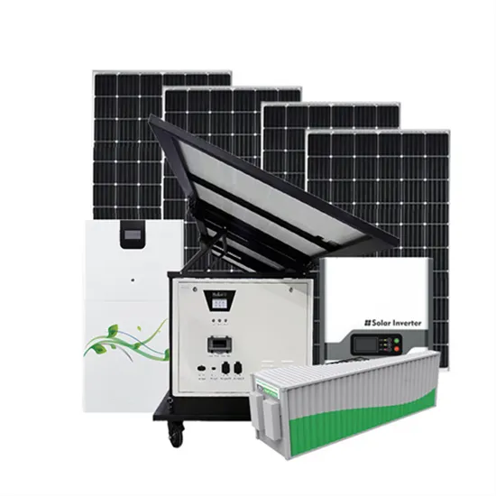
In the context of a DIY solar system like those found in camper vans or cabins, busbars help manage connections from solar panels, batteries, inverters, and charge controllers, allowing for a cleaner and more organized setup. What is the Purpose of a Busbar?
A terminal block, or battery busbar, is a specific type used in battery systems, including those in solar power installations. It serves a similar function as a regular busbar, but it is specifically designed to connect multiple batteries in a battery bank.
Wiring a busbar in a solar power system involves connecting the various components of the system, such as the solar panels, charge controller, and batteries, to the busbar. Here’s a general guide on how to wire a busbar: Mount the Busbar: First, mount the busbar on a non-conductive, fire-resistant surface.
In most systems, more than three leads will go to the battery. Therefore a busbar is required. Sizing a busbar for off-grid solar applications involves several factors, including the maximum current that the busbar will need to carry, the material of the busbar, and the allowable temperature rise. Here’s a general guide on how to size a busbar:
A busbar is a distribution point in an electrical system. It consolidates multiple electrical connections into a single point, facilitating power distribution from and to various components like the battery, charge controller, inverter, and a DC fuse box. 1. Sizing
The busbar should be located close to your battery bank and inverter to minimize the length of the cables and thus reduce power loss. Connect the Battery: Connect your battery to the busbar. Again, the positive terminal should be connected to the positive busbar and the negative terminal to the negative busbar.