Three diagrams with photovoltaics and energy storage – Hybrid, Off Grid, Grid-Tied with Batteries. In this article, you will find the three most common solar PV power systems for domestic and commercial use. For

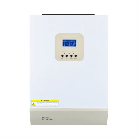
With the increasing emphasis on renewable energy sources, solar power has gained significant popularity in recent years. Hybrid solar inverters play a crucial role in converting solar energy
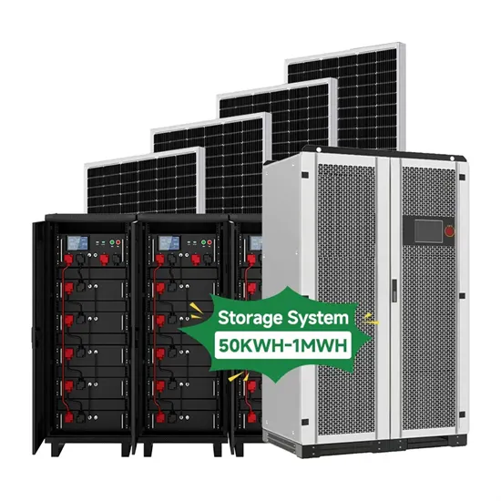
Solar battery storage: The next best step for solar PVwe install for passionate people. Customers who want to save the planet and be self-sufficient. Everyday, over 5,000 valuable One Vision customers monitor their solar PV systems
A solar panel wiring diagram (also known as a solar panel schematic) is a technical sketch detailing what equipment you need for a solar system as well as how everything should connect together. There''s no such
Navigating through the circuit diagram of a PV system with storage reveals the meticulous planning and understanding required to harness solar energy effectively. Whether it''s correctly connecting solar modules,
For example, residential grid-connected PV systems are rated less than 20 kW, commercial systems are rated from 20 kW to 1MW, and utility energy-storage systems are rated at more than 1MW. Figure 2. A common
Battery wiring diagrams: The following diagrams illustrate how to get increased current (more power) by using parallel wiring and how to increase voltage levels by using series wiring. You can do both using series and parallel wiring in
Schematic diagrams of Solar Photovoltaic systems. Self-consumption kits with batteries Self-consumption kits Plug & Play Kits 12V kits with batteries Motorhome / boating kits Autonomous lighting kits Anti-cut kit Hybrid inverter
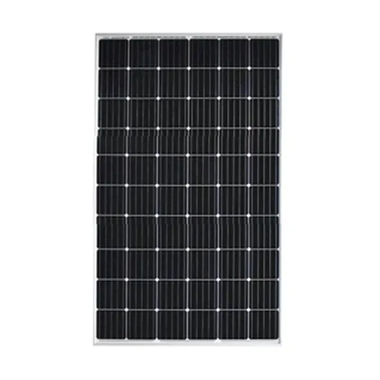
Solar Energy Storage; Solar Plus; Regions. Solar Energy in United States; Solar Energy in China; There are three wiring types for PV modules: series, parallel, and series-parallel. I assume you have a good
Key phrases: properly size, battery bank, solar power system, energy storage capacity, expected load, daily solar energy generation, desired autonomy, batteries required. In summary, the
A solar panel wiring diagram (also known as a solar panel schematic) is a technical sketch detailing what equipment you need for a solar system as well as how everything should connect together. There’s no such thing as a single correct diagram — several wiring configurations can produce the same result.
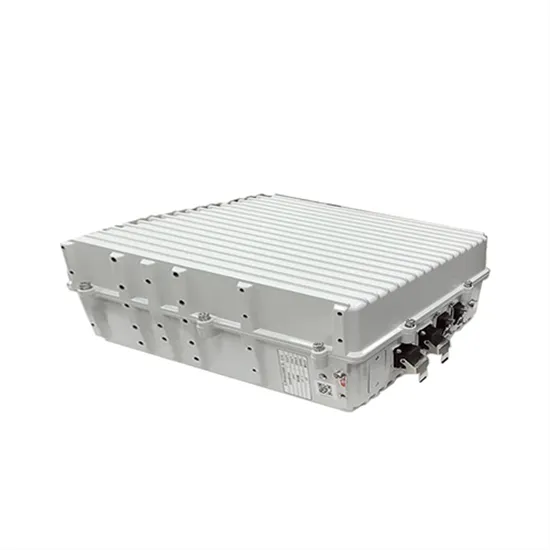
Self-Consumption: The PV system and battery are optimized to enable maximum self-consumption of energy produced by the PV system. The battery's capacity caters to home loads to minimise energy import from the grid.
12V is the most common solar panel wiring connection with batteries, as most appliances are designed to operate on 12V. With a 12V system, parallel orientation is usually preferred for both panels and batteries. This is because increasing the amps allows for devices to be powered for much longer than they could be when wired in series.
Batteries for solar power systems are available in 2, 4, 6, and 12 volts, so any combination of voltage and power is possible. Try this yourself using the Battery Bank Designer with 4 easy point & click choices. See complete circuit diagrams of example Solar Energy Systems.
lts in a system with a single PV battery grid connect inverter (as shown in Figure 1. These systems will be referred to as “hybrid” throughout the guideline. It requires replacing the existing PV inve ter with a multimode inverter if retrofitted to an existing grid-connected PV system.Figur
For simplicity we draw a single phase system but the concept is applicable for three phase system with one (3-phase) or multiple inverters in parallel. Grid will support entire load requiments if the power demand exceed the inverter peak power. Diagram C: Solar PV Power System with Grid-Tied Inverter & Feed In Tariff.