Connection to/from the Connection Unit: o. 450V DC to BAT connector (DC- and DC+ connections) corrected in the connection diagram o. Added a diagram of LG battery connection to inverter with 3 DIP switches l. In Configuration Menu Options: o. Power Control section: n. Removed Phase Balance link and info n
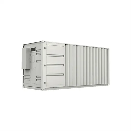
StorEdge Connection Unit for ROW Model: BCU-1PH-RWS Pxxx (Where xxx is any number,0-9,up to a maximum value where xxx = 350) Manufactured by SolarEdge Technologies Ltd. 6 Ha''Harash Street, Hod Hasharon 45240, Israel Tel: +972-9-9576620 A sample of the above product has been tested by our Laboratory in January-March 2016 and is found to be
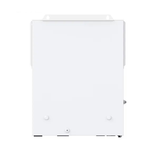
STOREDGE TM. StorEdge. TM. Single Phase Inverter . for Europe, APAC & South Africa. SE5000-XXS / SE6000-XXS. solaredge . Dimensions with Connection Unit (HxWxD) 962 x 315 x 184 mm: Weight with Connection Unit 26.5: kg Cooling : Natural convection and internal fan (user replaceable) Noise
4 天之前· On the Select a Unit screen, the total amount of fees will be shown for each unit. When hovering over the fees total, customers will see a breakdown of all fees included in the total. On the Customize Your Unit step, all fees will be shown in the Rental Information summary. Fees shown in the Rental Center can be edited in storEDGE.
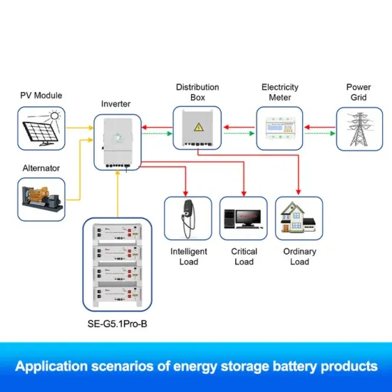
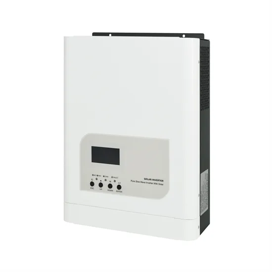
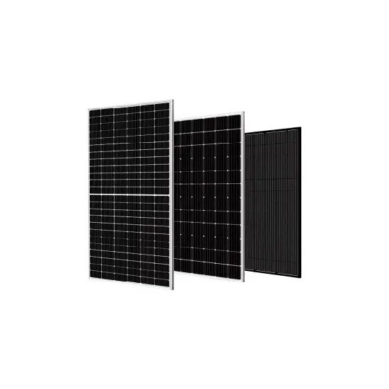
StorEdge Solution Components Energy Hub inverter - manages battery and system e nergy, in addition to its traditional functionality as a DC-optimized PV inverter. The . StorEdge Connection Unit, located at the bottom of the inverter, allows simple installation and connectivity to other system components and includes a DC Safety Switch.
Adding units to existing unit groups. Adding units to existing unit groups is simple. To do so: From your Unit Settings, click Add New Units. Fill out the range of unit numbers you''d like to add. Then, click Add to Unit Group. On the next screen, select the unit group to which you''d like to add your units. Then, click Select Group.
StorEdge Connection Unit Interfaces 19 Opening Conduit Knockouts 20 Mounting the Inverter 22 Chapter 4: Auto-transformer and Backed-up Loads Panel Installation (for Backup Only) 24 Mounting the Auto-transformer 25 Installing the Backed-up Loads Panel 25
The StorEdge Connection Unit, located at the bottom of the inverter, allows simple installation and connectivity to other system components and includes a DC Safety Switch. The SolarEdge Electricity Meter - The meter is used by the inverter for export/ consumption readings, and for S mart Energy Management applications, such as: export
The storEDGE rental center is a user-friendly interface that allows your customers to rent a storage unit and move in anywhere, anytime, and on any device! Toggle navigation and complete the entire move-in process in mere minutes, all from any device with an internet connection. Whether you provide a self-serve station at your facility or
To those participating in the comments, due to the company or person mentioned in the title, this is a reminder of the subreddit rule: Crusading is not welcomed here - If your sole or majority participation is to promote or denigrate one company in particular (or the person behind it), it may result in a ban. These kinds of participants too often resort to hyperbolic comments and
Page 1 StorEdge Inverter Installation Guide For Smart Energy Management using LG Chem batteries For Europe, APAC, Australia and South Africa Version 1.1...; Page 2 Added a caution about not altering the StorEdge Connection Unit enclosure: SolarEdge does not permit opening or puncturing the StorEdge Connection Unit in any location other than the pre- defined drill guide
All recurring promotions on the original unit will automatically transfer to the new unit. Promotions that are fixed to a set number of months will not be transferred. ⚠ The total monthly price of the unit will be updated automatically when you
StorEdge Connection Unit in any location other than the pre-defined drill guide locations, or otherwise altering the construction of the enclosure, as this may compromise safety and will void the warranty. Connection to/from the Connection Unit: 450V DC to BAT connector (DC- and DC+ connections) corrected in the connection diagram
StorEdge Connection Unit Interfaces 19 Opening Conduit Knockouts 20 Mounting the Inverter 22 Chapter 4: Auto-transformer and Backed-up Loads Panel Installation (for Backup Only) 24 Mounting the Auto-transformer 25 Installing the Backed-up Loads Panel 25
Unit types tell the system how to classify the various units at your facility. These settings also factor into how your facility''s units will be grouped. From this page you can see a list of all enabled unit types in your account. To access your facility''s unit types list: Click the Settings Tab in the lower left of your screen.

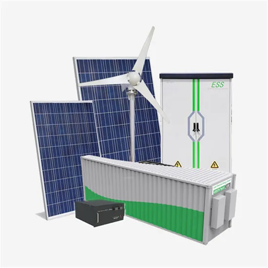
StorEdge Connection Unit for Energy Storage System (Up to 7.6kW single phase inverter) with PV Rapid . SolarEdge. Control Number: 4004590. Authorized by: for L. Matthew Snyder, Certification Manager. This document supersedes all previous Authorizations to Mark for the noted Report Number.
The storEDGE rental center is a user-friendly interface that allows your customers to rent a storage unit and move in anywhere, anytime, and on any device! Toggle navigation and complete the entire move-in process in mere minutes, all from any device with an internet connection. Whether you provide a self-serve station at your facility or
SE5000-RWS(1) StorEdge® Einphasen-Wechselrichter für DACH, Belgien und die Niederlande SE5000-RWS AC-AUSGANG (VERBRAUCHER/NETZ ) AC-Nennleistung 5000(2) VA Maximale AC-Leistung 5000(2) VA AC-Ausgangsspannung (Nennspannung), L-N(3) 220 / 230 Vac AC-Ausgangsspannungsbereich, L-N 184 - 264,5 Vac
Opening the StorEdge Connection Unit Covers 25 Installing the 9V Battery 26 Connecting the Strings to the Inverter 26 Connecting to the Battery 26 DIP Switch Setup 28 Battery Grounding 30 Connecting Communication to the Meter 31 Connecting to the AC Grid and to Backed-up Loads 33 Chapter 6: Commissioning the Installation 34
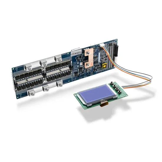
Appendix A: Troubleshooting StorEdge Connection Unit LEDs There are three LEDs on the lower board of the StorEdge Connection Unit, near the DIP switches: Figure 42: StorEdge Connection Unit LEDs l l l l In normal operation, the middle and bottom LEDs indicate auxiliary voltages (13V from DC/DC, 5V and 3.3V) and should always be lit.
All recurring promotions on the original unit will automatically transfer to the new unit. Promotions that are fixed to a set number of months will not be transferred. ⚠ The total monthly price of the unit will be updated automatically when you add insurance or services to the new unit. If you added a rental promotion, the review screen will
The checklist is suitable for a backup system with a single StorEdge Inverter, a single battery, an Auto-transformer and a single SolarEdge Electricity Meter installed at the grid connection point. For other system configurations, follow the steps in the StorEdge Installation Guide supplied with the StorEdge Inverter.
3. Position the new StorEdge Connection Unit below the inverter and from the inside of the inverter grab the AC and DC wires extending from the unit conduits. 4. Attach the StorEdge Connection Unit with its bracket to the wall and slightly
By default, all unit types have the 4000 - Rental Revenue account code assigned to them. To access your company''s unit type settings: Click the Corporate button in the upper right of your screen. From the Settings tab, click on the Software Settings tab and then the Unit Types button. Add a New Unit Type. Click the ⊕ New Unit Type button.
The StorEdge Connection Unit, located at the bottom of the inverter, allows simple installation and connectivity to other system components and includes a DC Safety Switch. One or two batteries (optional) - DC-coupled batteries designed to work with the SolarEdge system.
The StorEdge Connection Unit may have either external connections (MC4 connectors and cable glands), or utilize cable conduits for connections. Figure 7 shows both types. Connections to each of the unit types are described separately throughout this guide if the connection method is different.
Close the StorEdge Connection Unit external cover: Attach the cover and secure it by tightening the 12. Turn ON the StorEdge Connection Unit. If an additional external DC switch is installed between the power optimizers/ battery and the inverter(s) then turn it ON.
For proper sealing, first tighten the corner screws and then the two central screws. The following figure illustrates recommended order: 8. Close the StorEdge Connection Unit internal cover: Attach the cover and secure it by tightening the four screws with a torque of 1.2 N*m / 0.9 ft.*lb. 9.
Check all the communication cable between the StorEdge Connection Unit and the digital board in the inverter. There is a faulty wire connection or an internal error. Check the communication cable between the StorEdge Connection Unit and the digital board in the inverter. Check that the StorEdge Connection Unit LEDs are ON. Temp. Too High
Close the StorEdge Connection Unit cover(s). 1. Turn OFF the StorEdge Connection Unit ON/OFF switch. 2. Turn OFF the inverter ON/OFF switch, and wait until the LCD indicates that the DC voltage is safe (<50V), or wait five minutes before continuing to the next step. WARNING!