1 Introduction. Subsynchronous resonance (SSR) associated with the grid-connected wind turbine generators (WTGs) has drawn wide attention in recent years due to its detriment to the stability and safety of power system
The driving force and main causes of voltage instability are analysed. Different methods and devices used to enhance voltage stability are also explained. The steady-state and dynamic modelling of the power system
In the WindVSG demonstration, a GE-NREL team deployed controls for a 2.5-MW type-3 wind turbine drivetrain to provide primary frequency and voltage support and restabilize the surrounding grid by adjusting its power
To address issues like low inertia and vulnerability to voltage-drop faults in high-penetration new energy (wind–solar-storage) grid-connected power generation systems, this study implements virtual synchronous
Though installation of wind power into the existing power systems is increasing significantly, there is a possibility that a wind farm (WF) cannot be maintained stable and then it is decoupled from the grid according to the grid
This nifty little number represents the ratio of power extracted by the wind turbine to the total available power in the wind source., where . Remember, the Betz Limit is the highest possible value of, which is 16/27 or
suggested potential methods that can improve the voltage stability of wind farms: one is to install a static var compensator (SVC) to provide dynamic reactive power support, and the other is to select a doubly-fed
Designing of Fuzzy Controller to Stabilize Voltage and Frequency Amplitude in a Wind Turbine Equipped with Induction Generator P. Khani Maghanaki, A. Tahani the adaptive controller
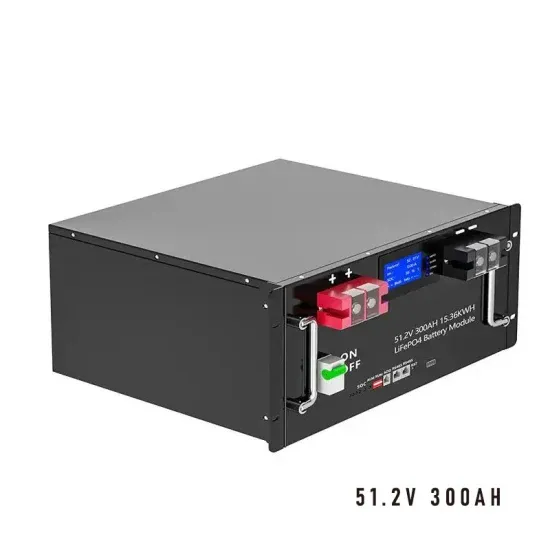
synchronous generator of 2 MVA with voltage regulator and the transformer. The characteristics of the wind turbine model are given in Table 4. Figure 6 Wind turbine model. Table 4 Wind
1. Adjust the generator voltage regulator: the voltage regulator of the generator can adjust the output voltage, by adjusting the voltage regulator to improve voltage stability. 2. Replace the voltage regulator: If you can not solve the
As various types of RESs are increasingly being connected to the electrical power grid, power systems of the near future will have more inverter-based generators (IBGs) instead
[ 22] suggested potential methods that can improve the voltage stability of wind farms: one is to install a static var compensator (SVC) to provide dynamic reactive power support, and the other is to select a doubly-fed induction generator (DFIG) that can control reactive power flexibly without installing reactive power compensation devices.
With a high penetration of wind power generation in a power system, wind turbines should provide more ancillary services like traditional synchronous generators. Thus, some voltage control methods, such as voltage droop control and QV control, have been proposed recently.
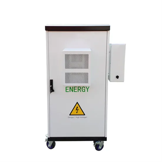
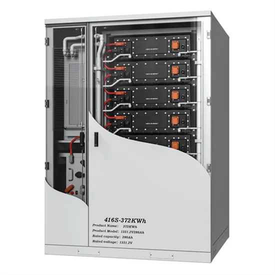
Using energy storage to assist wind turbines frequency and voltage regulation, the stability of grid-connected wind turbines is improved, and large-scale power failure accidents are avoided, which lays the foundation for the subsequent large-scale deployment of wind turbines in power system.
Wind turbines might not be able to provide sufficient reactive power support owing to the technology employed and the limited capacity of the grid to transmit power, leading to voltage instability. In addition, the intermittent nature of wind power and the limited fault response also contribute to voltage and system instability.
First, various voltage control methods of a wind farm were introduced, and they include QV control and voltage droop control. The reactive power of a wind turbine varies with active power, while the active power from each wind turbine may be different owing to wake effects.
Taking whether wind turbine has voltage support capability as a variable, the changes of system parameters after failure are compared between control strategy with frequency support assisted by supercapacitor (dotted line) and control strategy with voltage and frequency support assisted by supercapacitor (solid line), as shown in Fig. 6.