The plot of short-circuit current (ISC) and open-circuit voltage (VOC) describes the performance of the solar cell. This plot is shown in the figure below. As shown in the above graph, Initially, the
Download scientific diagram | Circuit diagram of a solar cell. from publication: Effects of partial shading on Photovoltaic with advanced MPPT scheme | The artistic response to Photovoltaic
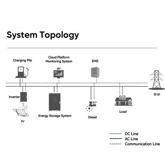
When it comes to installing a solar power system, understanding the wiring diagram is crucial. In a 3-phase solar system, the electrical power is distributed evenly across three alternating currents. This allows for efficient power

In the above regulated solar garden light circuit diagram, since the base of the left side 2N2222 emitter follower regulator BJT is clamped with a 5.1 V zener diode, means that its base voltage is fixed at 5.1 V, regardless of
About Us. This site is owned and operated by A Seed Forever LLC, a limited liability company headquartered in Washington State, USA. OffGridPermaculture is a participant in the Amazon Services LLC
Download scientific diagram | Schematic overview of a solar-powered sodium hypochlorite generator. The system is driven by silicon hetero-junction (series connection of multiple cells is
There''s rarely any need to be intimidated by solar panel diagrams. For portable off-grid power applications, EcoFlow''s RIVER series provides convenient plug-and-play power. If you''re looking for a whole home
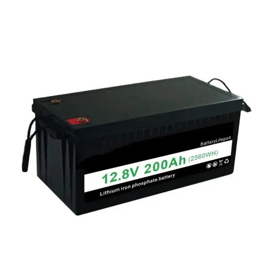
More solar input; You know how everything works; A good project to have in case of a blackout; Cheaper; Expandable; We are going to make our generator using the following steps: Choose a Battery; Choose an

A Single Line Diagram (SLD) (also know as Schematic Diagrams) is a simplified representation of the components in an electrical system and denotes how the components are laid out. It can also give key information on installation details
Photovoltaic generator. The photovoltaic generator is the set of solar panels and is the element that converts solar energy into electricity. These panels consist in small sheets of semiconductor material – the photovoltaic
So we''re going to give your ears a break by providing some relevant solar power diagrams that illustrate how solar power works. We start with a diagram of the solar cell and then proceed to
A solar panel wiring diagram (also known as a solar panel schematic) is a technical sketch detailing what equipment you need for a solar system as well as how everything should connect together. There’s no such thing as a single correct diagram — several wiring configurations can produce the same result.
Creating the photovoltaic system diagram represents an important phase in relation to assessing your solar PV system production levels. It’s fundamental to be able to size all system components as it affects the productivity and efficiency of the entire system.
What is a Single Line/Schematic Diagram ? A Single Line Diagram (SLD) (also know as Schematic Diagrams) is a simplified representation of the components in an electrical system and denotes how the components are laid out. It can also give key information on installation details including voltage and current of stringing in the system.
The power developed by the solar cell is calculated by multiplying current and voltage. And from that, we can draw a graph of power developed. As shown in the graph of developed power, at point P, the power is maximum. And we try to operate the panel at this point. This point is known as the maximum PowerPoint.
For the most part, solar generators utilize components that include comprehensive default protection. These modules display the specifics of the solar generator system, including battery state, charge rates, current draw, and component temperatures.
Creating precise photovoltaic system diagrams represents an important phase in relation to assessing your solar PV system production levels.