Vertical Installation: Standard Cable length: (Note: An extension cord is required at the rotor head of the double row assembly and the end of the single row.) Horizontal Installation: 60 type PV
Overall, a solar panel diagram with explanation PDF is a valuable resource for understanding the functionality and components of a solar panel system. It provides a visual aid for anyone interested in harnessing solar energy and can
between Ib and the front/back surface of vertical bifacial solar panels. It turns out that AOI of an east-west facing vertical bifacial solar panel can be simply expressed as (F ) = AOI front = cos
To meet the requirements of the DOE Zero Energy Ready Home program, provide an architectural drawing and riser diagram of RERH solar PV system components and solar hot water. Develop architectural drawings and
Indoor Installation Outdoor Installation . Locations where the yearly average high temperature. 1. is below 25˚C/77˚F 8" between inverters 8" between inverters 1.2" between inverters (if
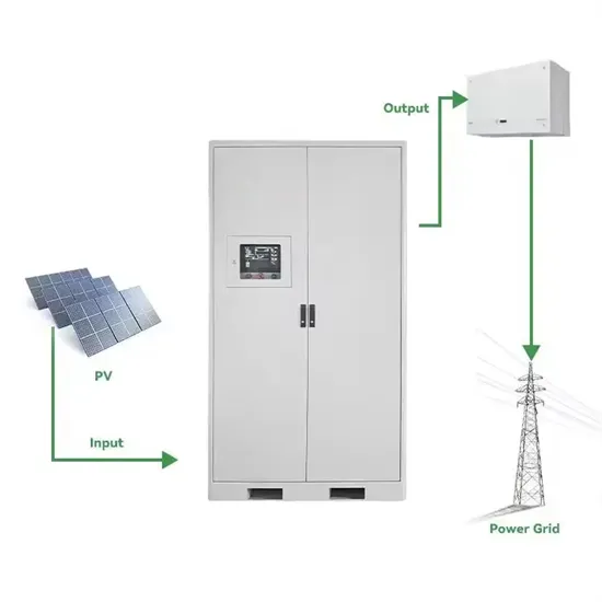
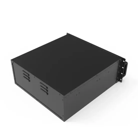
Components of a Solar Panel System. A solar panel system is made up of several key components that work together to generate and utilize solar energy. These components include: Solar panels: These are the most visible
How to calculate the Solar Panel Angle of your solar system? The solar panel angle of your solar system is different depending on which part of the world you are. Solar panels give the highest energy output when they are
There are two ways of arranging solar modules in photovoltaic power stations, horizontal and vertical. Horizontal means that the long side of the solar module is parallel to the east-west direction, while vertical means that the short side is
Learn how to wire a 12V solar panel system with this straightforward wiring diagram and step-by-step guide. Wiring a 12V solar panel typically involves connecting the positive and negative
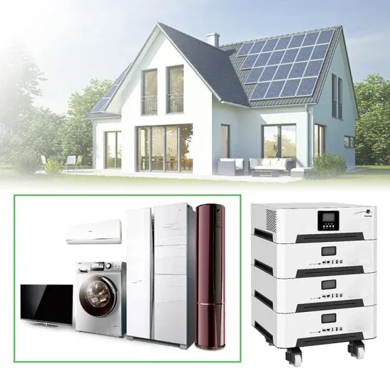
Mounting Harnessing the Sun: Detailed Guide to Installing Solar Panels on a Wall. Installation Tips, Advantages of Vertical Mount and More Home solar energy system owners have traditionally focused on installing panels on
See a complete example solar panel wiring diagrams done by Ecuip Engineering & Solar Design Lab here: Download Example Solar Panel Wiring Diagram. Understanding Solar Panel Wiring Diagrams. At the heart of every solar
See also: Solar Panels Vertical Or Horizontal (Which Orientation Is Best!) Step 1: Marking Roof Rafters. As simple as it may seem, marking roof rafters is an essential step. It involves locations, echo location, exploratory
Modules and PV systems should be installed by authorized and qualified personnel. Follow all safety precautions of all components used in the system. Long periods of shading on the module's surface from the sun can result in cell power dissipation and overheating. Do not clean the glass surface with chemicals.
The roofing PV system shall be installed after being evaluated by construction experts or engineers and with oficial analysis results for the entire structure. It shall be proved capable of supporting extra weight of system racking structures and PV modules.
The diagram should have sufficient detail to clearly identify: Figure 10: 70-Amp Double Pole Breaker. Figure 11: Site/System Diagram. The diagram should include: array breaker for use by the location, size, orientation, conduit size and location and balance of system solar PV system. component locations.
PV modules install under hot and humid weather condition. PV modules installation site is under long-term humid environment such as water floating application. To reduce the risk of PID, on the modules DC connection site, it is recommended to connect the negative to ground.
PV module installation site is exposed to long-term humid conditions such as floating PV system. To reduce the risk of PID, on the modules DC connection site, it is recommended to connect the negative to ground. As part of the module design, an anodized corrosion-resistant aluminum alloy frame is used to provide rigidity.
Tilt angle of PV modules refer to the included angle between module surface and horizontal ground. The module will obtain the maximum power output when directly facing the sunlight. Modules are preferred to be south-facing in the north hemisphere and north-facing in the south hemisphere.