By understanding the components and their connections in the diagram, homeowners and installers can successfully set up and maintain a 3-phase solar system for their energy needs. Understanding 3-Phase Solar System Wiring
Solar Module Cell: The solar cell is a two-terminal device. One is positive (anode) and the other is negative (cathode). A solar cell arrangement is known as solar module or solar panel where
Easy. Just connect the positive cable of the third solar panel to the negative cable of your 2-panel string. You can string together as many panels as you want like this. Step 4: Connect the Solar Panels to the Solar Charge
All about Solar Panel Wiring & Installation Diagrams. Step by step PV Panel installation tutorials with Batteries, UPS (Inverter) and load calculation Solar Panel Wiring Diagram and Installation Tutorials Electrical Technology. 18 1

A PV combiner box is an essential component of a solar photovoltaic (PV) system, allowing multiple PV strings to be connected and combined into one output. The wiring diagram for a PV combiner box outlines the connections

The 200 watt solar panel wiring diagram assumes 2 x 100w panels are being fitted. If you happen to be fitting 1 x 200w panel instead, see our 100 watt solar panel wiring diagram. We''ve included 2 diagrams below. The
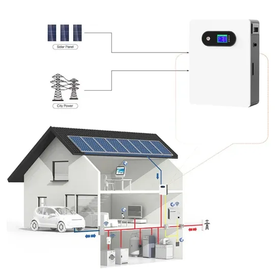
The inverter, in turn, is connected to the utility grid or electrical loads through another set of wires and cables. Solar Panel and Inverter Connection Diagram. The solar panel and inverter connection diagram illustrates the process of
At the heart of every solar energy system lies the solar panel wiring diagram, a blueprint that maps out the connections between various components such as solar panels, inverters, charge controllers, batteries, and electrical wiring.
This information can usually be found on the back of the solar panel or in the manufacturer''s specifications. 3. Connect the positive terminals of the solar panels: Take the positive terminal
It provides a clear and systematic guide for wiring connections, fusing, and grounding. Following the diagram will help ensure the safety, efficiency, and long-term performance of your solar
Even if you don''t do any harm, a smart solar panel wiring plan will optimize performance and maximize the return on your investment. Read on to find out more about solar panel connection diagrams and how to wire PV
Then insert the cable by the opposite end of the pin and finally press the crimping tool to properly crimp the MC4 solar connector to the solar cable. If you have a solar panel or a string series of PV modules that seem to
Most modern solar panel installations use single-conductor Photovoltaic (PV) wire, between 10 and 12 gauge AWG. Wiring is required to connect the solar panels to the charge controller, inverter, and battery (in an off-grid system).

The wiring diagram outlines the layout and connections for the panels, inverters, batteries, and other components in a solar power system. It provides a visual representation of how the system should be set up and connected to ensure
A solar panel wiring diagram (also known as a solar panel schematic) is a technical sketch detailing what equipment you need for a solar system as well as how everything should connect together. There’s no such thing as a single correct diagram — several wiring configurations can produce the same result.
When wiring solar panels, there are very specific types of cables and connectors that you’ll need to get the job done successfully. These include: PV Wire or Solar Cable: These are used to interconnect the solar panels which we have also referred to as stringing.
Wiring: To connect solar panels, a wiring system is used. There are two types of wiring systems commonly used: series wiring and parallel wiring. In series wiring, the positive terminal of one solar panel is connected to the negative terminal of the next panel. This allows the generated voltage to add up, resulting in a higher voltage output.
Wiring solar panels in series involves connecting each panel to the next in a line (as illustrated in the diagram above). Just like a typical battery that you may be familiar with, solar panels have positive and negative terminals.
Wiring solar panels together can be done with pre-installed wires at the modules, but extending the wiring to the inverter or service panel requires selecting the right wire. For rooftop PV installations, you can use the PV wire, known in Europe as TUV PV Wire or EN 50618 solar cable standard.
Also, note: the National Electrical Code (NEC) prohibits using regular cables in your solar panel installation. You need solar panel cables and wires designed specifically for the job at hand. Panel-wiring cable resists high-temperatures, flames, UV rays and moisture.