Download Busbar Sizing and Voltage Drop Calculation Excel Sheet xls. Download Free MEP Calculation Excel Sheets, AutoCAD Drawings, and Training Courses for HVAC, Firefighting, Plumbing and Electrical Systems
Also, there was no modification to the 120% rule with the adoption of NEC 2020. Further, it goes on to allow as much as 120% of a busbar''s rating to be exceeded. This is where the calculation comes into play. (Busbar Rating (A) x 1.2) - Main

The National Electric Code allows for a few different ways to interconnect PV systems to utility systems. In two editions of Code Corner, Ryan Mayfield with Mayfield Renewables, explains busbar, load side
To do this, use the following formula: Batteries needed (Ah) = Daily consumption (Ah) X Backup days X Annual correction factor 1.15 / DOD (%). For instance, if you have a daily consumption of 100 Ah, you want three

Theoretically if the panel is fully loaded with breakers of equal value totaling the rated limit of the main breaker/busbar, and the main breaker is at one end of the busbar, and the solar breaker is at the opposite end of the busbar, and the
A design is compliant where the sum of the ampere ratings of the PV supply and the branch/feeder overcurrent devices does not exceed the panelboard busbar rating. It is not necessary to consider the utility supply
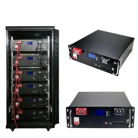
In a solar panel, there''s a thin strip of copper or aluminum between cells that conducts electricity called a busbar. It separates solar cells and conducts the direct current the cells collect from solar photons to the solar
There is a formula for that, however, it consists of the following estimation. Panel Power/ Panel Length x Panel Width x 100. Important points. Efficiency has a direct relation with the surface
We know that solar panels have about 20% efficiency. To calculate the solar panel or solar cell efficiency, we use the solar efficiency equation. We will look at how you can use this efficiency
In short, (B)(3)(1) is a calculation check against overcurrent hazard in a simple case: Take 125% of the rated continuous output current from one power source– say, one PV inverter- and then add this figure to the
I Have 4 Rich Solar panels 100W 5.41A Not a Big system by far, I have a Mars Charge Controller 1.200W Wind Solar 1,000W so-post to be auto censoring inverter 3KW 24v Hybrid inverter, my battery bank is Lithium Phosphate
Calculate the 150 x 25 mm busbar current carrying capacity in all the above materials, Copper bar carries 4500Amps (1.2 x 150 x 25) current; Aluminium Carries 3000 Amps (0.8 x 150 x 25) Current; GI Bus Bar Carries 2250 Amps
Further, it goes on to allow as much as 120% of a busbar’s rating to be exceeded. This is where the calculation comes into play. (Busbar Rating (A) x 1.2) - Main Breaker Rating (A) = Max PV (A) Let’s start with an example. We have a 200 Amp bus rating for our service panel. In it, we have a 200 Amp main breaker. 200A x 1.2 - 200A = 40A
In solar panels, busbars are typically flat strips, which allow heat to dissipate more efficiently because of their high surface area to cross-sectional area ratio. Insulators can support busbars, or insulation may completely surround them. In the solar industry, busbars are connected to solar panels by welded connections.
To comply with the 120% rule, the breaker must be connected to the end of the busbar (opposite end to the main breaker). This allows 120% of the busbar rating to be used for calculations. For example, a 200A busbar would be considered a 240A rating, in which case an inverter output up to 40A (125% of rated output current) can be added to the panel.
If a bus bar is rated at 225A, then the allowance under the NEC rule is 1.2*225 = 270A. With the existing system taking up 40A, then another 30A breaker could be installed for the second inverter. If not, the main breaker would need to be replaced with a 175A breaker.
The National Electric Code allows for a few different ways to interconnect PV systems to utility systems. In two editions of Code Corner, Ryan Mayfield with Mayfield Renewables, explains busbar, load side interconnections in 705.12 (B) (3) (1) and (2), and then supply side connections in 705.11 (C) and (D).
When the load becomes greater than the current provided by solar, the grid must supplement to cover the load. If the current load exceeds the sum of the main break and the solar breaker, the busbar's published current limit could be exceeded.