grid-connected inverter, the photovoltaic grid-connected inverter system is simulated by Matlab software. The snubber resistance of the switch is set to 0.00005 Ohms. The grid voltage peak
Architectures of a PV system based on power handling capability (a) Central inverter, (b) String inverter, (c) Multi‐String inverter, (d) Micro‐inverter Conventional two‐stage
The control parameters of active and reactive links of photovoltaic inverter are optimized and calculated by means of particle swarm optimization algorithm and simulation. The results are
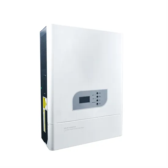
Photovoltaic (PV) grid-connected inverter is the core component of PV generation system; quickly and accurately obtaining the parameters of inverter controller has great significance in analysis of transient characteristics
Grid-tied PV systems are typically made of strings of series-connected PV modules; one or more strings (thus composing a PV array) feed a dc/dc or a dc/ac converter. Assuming that all the modules are identical and the
The typical main circuit of PV inverter includes inverter bridge and filter. Parameters of each element in a large-scale grid-connected PV power plant are shown in Table 1. Cable parameters of electricity collection
1 INTRODUCTION. With the rapid development of distributed generation technologies, a large number of renewable energy sources, such as wind power, photovoltaic power and energy storage, are connected to the
Environmental parameters of the PV arrays The expectancy value of r is set as 0.03 Ω in the simulation model to make the set value applicable to various dip levels. After that, S and T can be solved under different test conditions based on the accurate modelling of point M first.
In the case that the PV inverter control strategy and parameters are not disclosed, a method is proposed to realise the identification of the three types of parameters through the LVRT test. The method can solve the difficulty in performing the tests of Groups 2 and 3 parameters in the field.
The line resistance r is connected to the output end of the PV array to simulate the equivalent impedance of the actual array collection circuit. Table 4. Main parameters of the PV inverter In Fig. 8, a comparison of the test results and simulation results under the voltage dip conditions of 0 pu H, 0 pu L, 0.35 pu H, and 0.20 pu H were made.
In the failure mode, the PV inverter operates at point G 1 (actual operating point) when r = 0.042 Ω, and the DC voltage rises by 111 V. The PV inverter operates at G 2 when r = 0 Ω, and the DC voltage rises by 98 V. A noticeable difference of 11.7% exists between the two operating points.
The operating condition of 0.35 pu H is regarded as an example to verify the necessity of the equivalent resistance r. Fig. 5 shows the PDC − VDC curves with r = 0 Ω and r = 0.042 Ω, respectively. In the failure mode, the PV inverter operates at point G 1 (actual operating point) when r = 0.042 Ω, and the DC voltage rises by 111 V.
According to the model, a photovoltaic system can consist of up to four subarrays, each with its own set of parameters for tracking, surface angles, shading and soiling, and DC losses. The modeled system must consist of a single type of photovoltaic module and a single type of inverter – it cannot combine different sizes or brands of modules and inverters.