step in the design of a photovoltaic system is determining if the site you are considering has good solar potential. Some questions you should ask are: • Is the installation site free from shading
Under three typical working conditions, the maximum stress of the PV bracket was 103.93 MPa, and the safety factor was 2.98, which met the strength requirements; the hinge joint of 2 rows
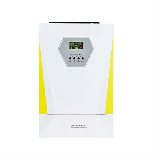
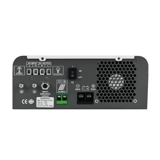
Follow the wiring diagram to connect the panels to the inverter, which converts the DC power generated by the panels into usable AC power for your home. Finalizing the Installation. Once the panels are securely mounted
Review the mounting options discussed in section two of this guide for alternatives. 11. Measure the distance between the estimated locations of all system components and develop site drawing and one-line diagram of PV
In addition, the homeowner should be provided with a one-line electrical riser diagram of the PV system components. The diagram should have sufficient detail to clearly identify: Configuration of the PV array; Conduit size and type;
6. Drive mechanism: This component, found in solar trackers, includes gears, motors, and controllers that drive the motion of the panels to follow the sun. 7. Electrical boxes and wiring conduits: These are used to house electrical
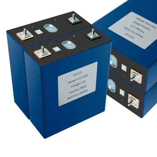
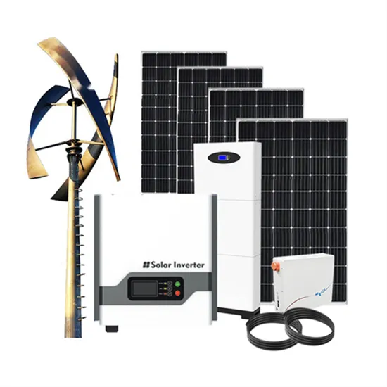
The heart of a photovoltaic system is the solar module. Many photovoltaic cells are wired together by the manufacturer to produce a solar module. When installed at a site, solar modules are wired together in series to form strings. Strings of modules are connected in parallel to form an array.
When the solar photovoltaic module is connected in parallel with the bypass diode, the current in the system will flow directly through the diode, so as to bypass the blocked part of the solar photovoltaic module and minimize the heating degree and power consumption of the solar photovoltaic module. Each module has three diodes.
MOUNTING INSTRUCTIONS PV modules can be mounted to the substructure using either corrosion-proof M8 bolts placed through the mounting holes on the rear of the module or specially designed module clamps. A clearance of at least 115mm (recommended) is provided between modules frame and the surface of the wall or roof.
Risen module should be installed in the following environmental conditions. -20°C to+50°C. Remarks: The working environment temperature is the monthly average maximum temperature and minimum temperature of the installation site. The mechanical load bearing capacity of the solar PV module is determined based on the installation method.
Insert the end clamps laterally in the pedestal. The end clamps are attached and then tightened at the height of the module frame. Modules should be installed to the Solar Stack pedestals with the manufacturer approved middle/end clamps. There are different types of clamps available for the module installation.
Warning: Any electrical maintenance must shut down the PV system firstly. Improper system maintenance may cause fatal dangers such as electric shock and burning. Dust accumulation on the glass surface of the module will reduce its power output and may cause hot spots. So the surface of photovoltaic modules should be kept clean.