Currently the combiner boxes are only possible in the DC part of the circuit. If the DC cables in the ''Ohmic losses'' dialog have been defined via the ''Detailed computation'' tool there can be one
Download scientific diagram | Schematic illustration of the dielectric energy-storage characteristics of linear dielectric, nonlinear dielectric and bilayer linear/nonlinear dielectric composites.
Download scientific diagram | a) Schematic illustration of the dielectric energy‐storage characteristics of the asymmetric LTN structure. b) Fabrication process of the single‐layer and
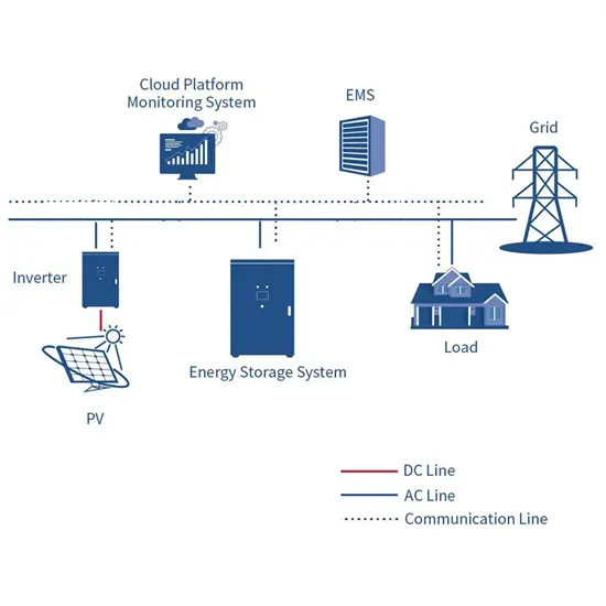
Understanding Grid Tie Solar System Wiring Diagram. When it comes to installing a grid tie solar system, understanding the wiring diagram is crucial. The diagram provides a visual representation of how the different components of the
Download scientific diagram | The schematic representation of the energy storage mechanisms with their electrochemical signatures (CV and CD curves): (a and n) hybrid supercapacitor (b–d
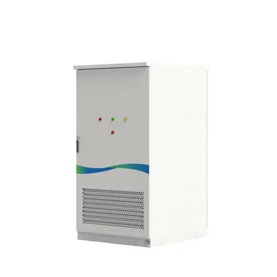
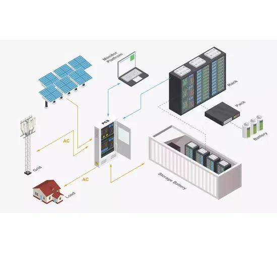
gh the Power Conversion Sys-tem is collected by DC Combiners (in some cases also by a DC Recombiner).The D Combiner is a switchboard where several battery racks are placed in parallel itching to segregate the group of battery racks from the rest of the BESS (range of th
The DC-Coupled system’s dedicated DC re-combiner has a number (here 5) of DC inputs that matches the maximum number of combiner boxes that can be connected to it. It has a second type of fused input connection that connects to the DC/ DC converter and a fused output that connects to the inverters.
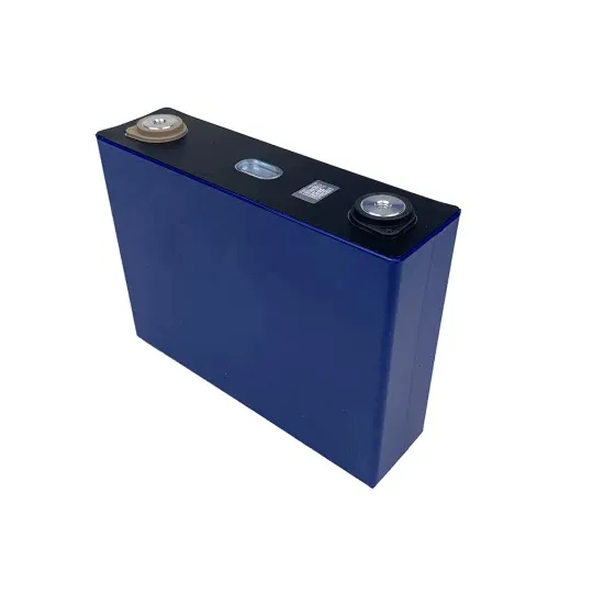
As a result, battery energy storage systems (BESSs) are becoming a primary energy storage system. The high-performance demand on these BESS can have severe negative effects on their internal operations such as heating and catching on fire when operating in overcharge or undercharge states.
This document provides site surveyors and design engineers with the information required to evaluate a site and plan for the Enphase EnsembleTM energy management system. The information provided in the documents supplements the information in the data sheets, quick install guides and product manuals.
The following sample Enphase Energy System diagrams help you design your PV and storage systems. Size the production RCD to the production circuit size or higher. System size: PV: 3.68 kW AC. Storage: 5 kWh. Size the production RCD to the production circuit size or higher. System size: PV: 7.36 kW AC. Storage: 20 kWh.
The three cases of distributed generation and battery storage are considered simultaneously. The proposed method is applied to the test grid operator IEEE with 37 buses, and reductions in annual energy losses and energy exchange are obtained in the ranges 34–86% and 41–99%, respectively.