Grid-connected PV systems allow homeowners to consume less power from the grid and supply unused or excess power back to the utility grid (see Figure 2). The application of the system will determine the system

The block diagram of a solar inverter illustrates its essential components and their functions. Understanding the block diagram helps grasp the working principle and functionality of a solar inverter. Key components in the

How to Design and Install a Solar PV System? With Solved Example; Related Posts: Wiring and Installation; Electrical Wiring; UPS / Inverter Wiring Diagrams & Connection; Batteries Wiring Connections and Diagrams; Single Phase &
Medium-sized solar power systems – with an installed capacity greater than 1 MWp and less than or equal to 30 MWp, the generation bus voltage is suitable for a voltage level of 10 to 35 k V. Large solar power systems – with an installed
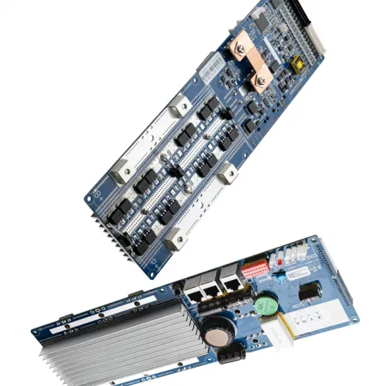
An inverter PCB diagram is a graphical representation of the components and connections on a printed circuit board (PCB) used in an inverter. The diagram provides a visual guide for technicians and engineers to understand the layout
Solar Design Lab automatically generates wiring diagrams that illustrate the connections between components, including panels, inverters, batteries, and electrical wiring. These diagrams are fully compliant with local building codes
As we can see from this solar power diagram, however, we need more than just solar panels to complete a full solar power system installation. The following items are also required: A Solar
An adequately sized PV service disconnect box must be used prior to making the connection between the junction box and the solar inverter. By connecting on the Line side, it avoids de-rating the existing service panel and avoids back-feed
The solar panel and inverter connection diagram illustrates the process of connecting a solar panel to an inverter in a solar power system. This connection allows the conversion of the DC power generated by the solar panel into AC

Designing a solar inverter circuit essentially requires two parameters to be configured correctly, namely the inverter circuit and the solar panel specs. The following tutorial explains the details thoroughly. Contents
Schematic diagrams of Solar Photovoltaic systems. Have you decided to install your own photovoltaic system but don''t know where to start? We have produced a number of connection diagrams for the various components of a solar
A solar inverter converts the DC power output from solar panels into AC power for various applications. The block diagram of a solar inverter illustrates its essential components and their functions. Understanding the block diagram helps grasp the working principle and functionality of a solar inverter.
The solar panel and inverter connection diagram typically includes labels and symbols to indicate the different components and their connections. The solar panels are connected to the inverter through a series of wires and cables, which may include circuit breakers, combiner boxes, and other electrical components.
The inverter, in turn, is connected to the utility grid or electrical loads through another set of wires and cables. The solar panel and inverter connection diagram illustrates the process of connecting a solar panel to an inverter in a solar power system.
A solar inverter is an electrical converter that changes the direct current (DC) output of a solar panel into alternating current (AC) that can be used for various applications. It is an essential component in a solar power system, responsible for converting and monitoring the power generated by the solar array. How does a solar inverter work?
Designing a solar inverter can be a complex process that involves a good understanding of electronics, power systems, and solar energy. Here are some general steps to consider when designing a solar inverter: Determine the load requirements: The first step in designing a solar inverter is to determine the load requirements.
A solar panel wiring diagram (also known as a solar panel schematic) is a technical sketch detailing what equipment you need for a solar system as well as how everything should connect together. There’s no such thing as a single correct diagram — several wiring configurations can produce the same result.