With the current drive towards sustainable energy, free solar inverter circuit diagrams are a crucial resource for anyone looking to build a solar energy system. Such diagrams provide an invaluable step-by-step guide on
100w Inverter Circuit Schematic Eeweb. Schematic Diagram Of The Basic Inverter Circuit Scientific. Solar Panel Sine Inverter Mppt 36v To 230v Schematic Diagram Circuit. Simple 48v Inverter Circuit Homemade Projects.
In summary, the schematic diagram of a solar power system illustrates the flow of energy from the solar panels to the charge controller, batteries, inverter, and optional backup generator. This diagram serves as a visual guide in
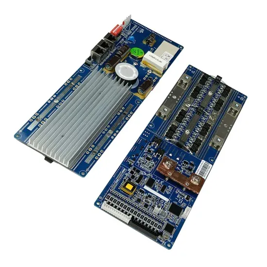
1. Input Filter – the input filter removes any ripple or frequency disturbances on the d.c. supply, to provide a clean voltage to the inverter circuit.. 2. Inverter – this is the main
In conclusion, the CMOS inverter schematic diagram is a vital component in digital integrated circuits, responsible for converting and amplifying electrical signals. By utilizing the complementary behavior of the NMOS and PMOS
Designing a solar inverter circuit essentially requires two parameters to be configured correctly, namely the inverter circuit and the solar panel specs. The following tutorial explains the details thoroughly. Contents
Before jumping into the inverter circuit diagram, it is necessary to know the logical symbol of the power inverter. In the electronics or logic design subject, the inverter is also known as the NOT
Advantages and Disadvantages of Solar Power Plant. Advantages . The advantages of solar power plants are listed below. Solar energy is a clean and renewable source of energy which is an unexhausted source of energy. After
At [Brand], we understand the importance of harnessing clean and renewable energy sources. In this comprehensive guide, we will explore the world of solar power inverter circuit diagrams and provide insights tailored to
Everything You Need to Know about IGBT Inverter Circuit Diagrams IGBT inverter circuit diagrams are a type of wiring diagram used to understand the electrical components and connections of an inverter. An

Construction of Circuit. There are five stages of this Circuit: PV Solar panel; Battery Charger ; Switching Pulse Oscillator; Switching Device; Step Up transformer; Solar Panel. This PV Solar Inverter Circuit uses a 12-volt/20
Solar Inverter Circuit Diagram: To understand well how to construct a solar inverter, it is vital to study how the circuit operates through with the help of following steps: N1 & N2 gates of IC 4049 are employed as an
There are five stages of this Circuit: This PV Solar Inverter Circuit uses a 12-volt/20-watt solar panel to obtain input bias. When exposed to the open Sun, the solar panel produces a peak output of 12 volts at 1600 mA.
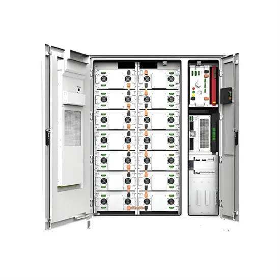
The solar inverter receives inputs from 20 PV strings. The inputs are grouped into 10 MPPT circuits inside the solar inverter to track the maximum power point of the PV strings. The DC power is then converted into three-phase AC power through an inverter circuit. Surge protection is supported on both the DC and AC sides.
Designing a solar inverter can be a complex process that involves a good understanding of electronics, power systems, and solar energy. Here are some general steps to consider when designing a solar inverter: Determine the load requirements: The first step in designing a solar inverter is to determine the load requirements.
A typical PV grid tied inverter uses a boost stage to boost the voltage from the PV panel such that the inverter can feed current into the grid. The DC bus of the inverter needs to be higher than the maximum grid voltage. Figure 20 illustrates a typical grid tied PV inverter using the macros present on the solar explorer kit. Figure 20.
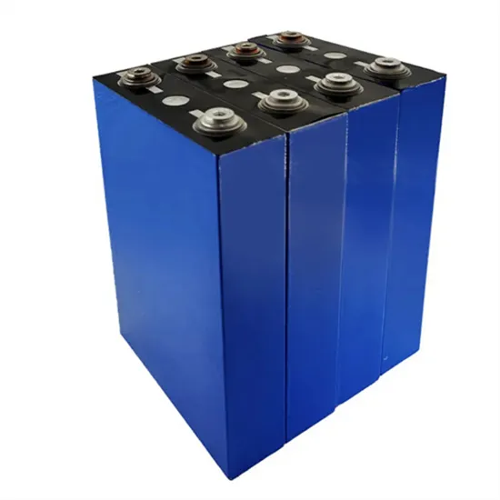
The solar panel or PhotoVoltaic (PV) panel, as it is more commonly called, is a DC source with a non-linear V vs I characteristics. A variety of power topologies are used to condition power from the PV source so that it can be used in variety of applications such as to feed power into the grid (PV inverter) and charge batteries.
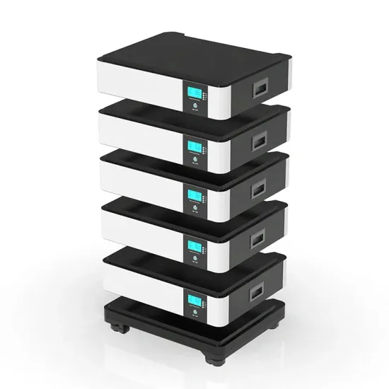
Solar inverters are also called as photovoltaic solar inverters. These devices can help you save lot of money. The small-scale grid one have just two components i.e. the panels and inverter while the off grid systems are complicated and consists of batteries which allows users to use appliances during the night when there is no Sunlight available.