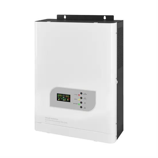
The inverter is an electrostatic converter that is used to transform the direct current output to alternating current (DC/AC static converter). Inverters are chosen according to the panel configuration and characteristics.
A hybrid solar inverter wiring diagram is a visual representation of the electrical connections involved in a hybrid solar power system. It showcases the integration of solar panels, batteries,
A circuit diagram of a parallel inverter is a type of electrical diagram that shows the flow of electricity through the components of a solar energy system. It includes parts such as the solar panels, the inverter, and the
The inverter PCB board is an essential component in various applications such as solar power systems, uninterruptible power supplies (UPS), motor drives, and other power conversion systems. and short circuit protection to prevent any
Fig. 1: Schematic diagram of photovoltaic plant. Module junction boxes connect solar cells to the outside world by joining the connection cables of the cell strings and interconnecting them with
The MPPT solar inverter circuit diagram is a crucial component in any solar power system. It is responsible for efficiently converting the DC electricity generated by the solar panels into AC
Download scientific diagram | The control system schematic diagram of PV inverter: off-grid mode and grid-connected mode. from publication: The application of hybrid photovoltaic system on
The on grid inverter circuit diagram typically consists of several key components, including the solar panels, DC isolator, MPPT charge controller, inverter, grid connection, and electrical protection devices.
Intensive efforts have been made to articulate the strategies of eliminating or reducing harmonics distortions generated due to output of this conversion. This study aims to investigate the
The diagram typically includes the different components of a solar panel system, such as the photovoltaic cells, inverter, battery, and electrical connections. Photovoltaic cells: These cells are the main components of a solar panel and
Overview of the on-grid inverter circuit diagram. An on-grid inverter circuit diagram is an essential component of a solar energy system that is connected to the utility grid. It converts the direct current (DC) produced by the solar panels
A voluntary solar power supply circuit and a transformer may be added within to charge the battery when necessary (check diagram). Solar Inverter Circuit Diagram: To understand well how to construct a solar inverter,
This paper consists of three parts. In the first part, the modelling of leakage current paths in the module package is discussed. The PID mechanisms in both c-Si and thin-film PV modules are also comprehensively reviewed. The
Solar panels, also known as photovoltaic (PV) panels, are the primary component of an on grid inverter circuit diagram. These panels contain multiple solar cells that convert sunlight into DC electricity through the photovoltaic effect. 2.
Creating the photovoltaic system diagram represents an important phase in relation to assessing your solar PV system production levels. It’s fundamental to be able to size all system components as it affects the productivity and efficiency of the entire system.
The on grid inverter circuit diagram typically consists of several key components, including the solar panels, DC isolator, MPPT charge controller, inverter, grid connection, and electrical protection devices. Let’s explore each of these components in more detail: Solar panels: These are the primary source of DC power in the system.
Choice of the inverters characteristics and size is fundamental for the system’s overall performance. During composition of the photovoltaic wiring diagram, I would really recommend you try a photovoltaic software capable of activating, sizing and configuring the inverter and all other solar PV system devices.
In a PV system, an inverter is an essential part of the balance of system (BOS), which converts the DC output into AC output.
A typical PV grid tied inverter uses a boost stage to boost the voltage from the PV panel such that the inverter can feed current into the grid. The DC bus of the inverter needs to be higher than the maximum grid voltage. Figure 20 illustrates a typical grid tied PV inverter using the macros present on the solar explorer kit. Figure 20.