BESS is connected to the Hawaii Island electrical grid at the point of common coupling with a 10.6 MW wind farm that is owned and operated by the Hawi Renewable Development (HRD) in the northern
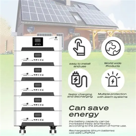
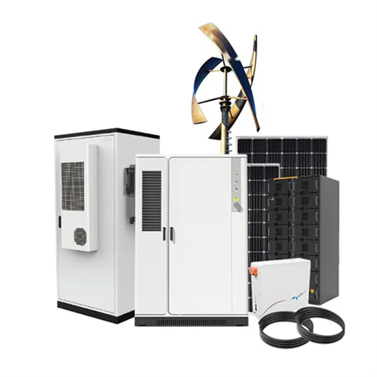
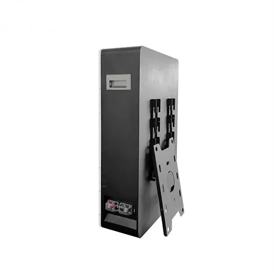
This makes BESS a more affordable option. Government initiatives and rebates have further reduced the payback period, making BESS accessible for residential and commercial use The System Structure of a Battery Energy Storage System. A BESS comprises several integral components, each crucial for maintaining efficiency and safety. The Image
Download scientific diagram | Traditional PV+BESS system: (a) circuit representation; (b) power smoothing methods implementation principle. from publication: Comparative Study of Ramp-Rate Control
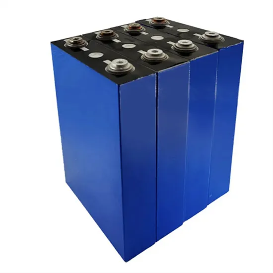
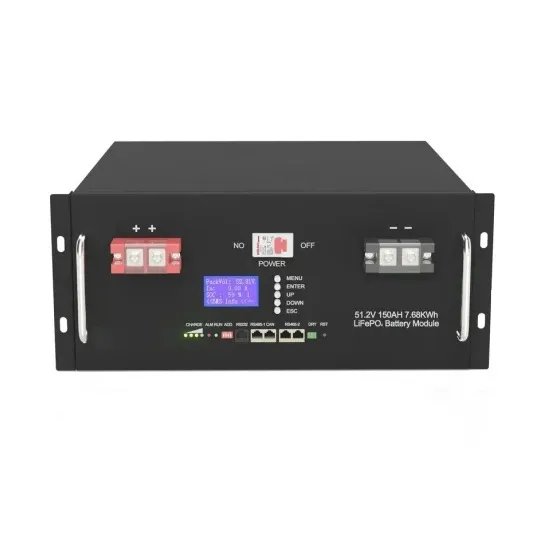
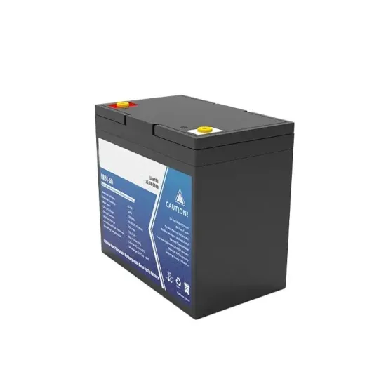
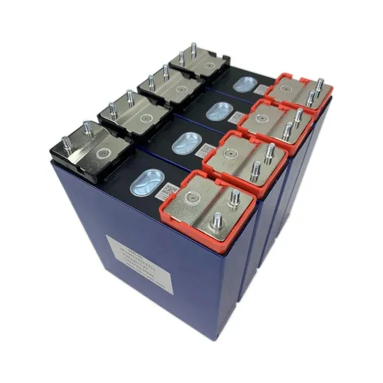
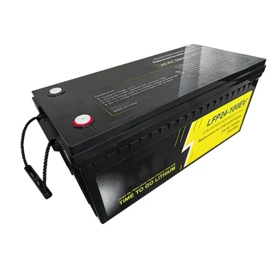
Lithium iron phosphate battery (LIPB) is the key equipment of battery energy storage system (BESS), which plays a major role in promoting the economic and stable operation of microgrid.
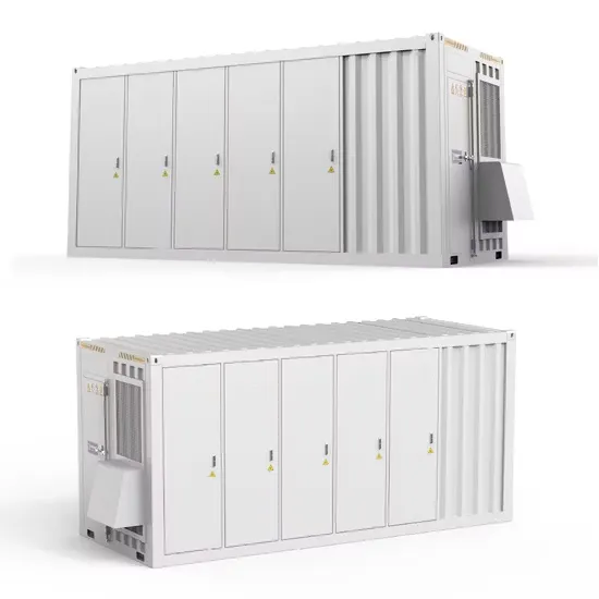
The system uses seven linked EVLOFLEX BESS modules. Enerflex provided the integration of BESS into the balance of plant which included the engineering, design, installation, and commissioning. Outcome As an EVLO Certified Turnkey Solution Provider, Enerflex''s turnkey BESS system gave the project cost certainty and minimized risk. Enerflex
A BESS is composed of different "levels" both logical and physical. Each specific physical component requires a dedicated control system. Below is a summary of these main levels: The battery system is composed by
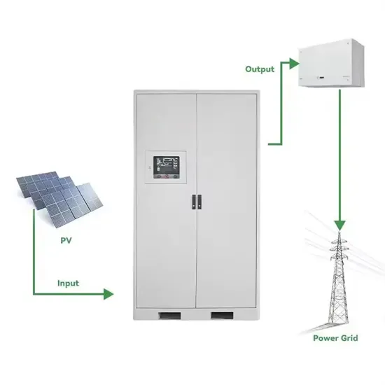
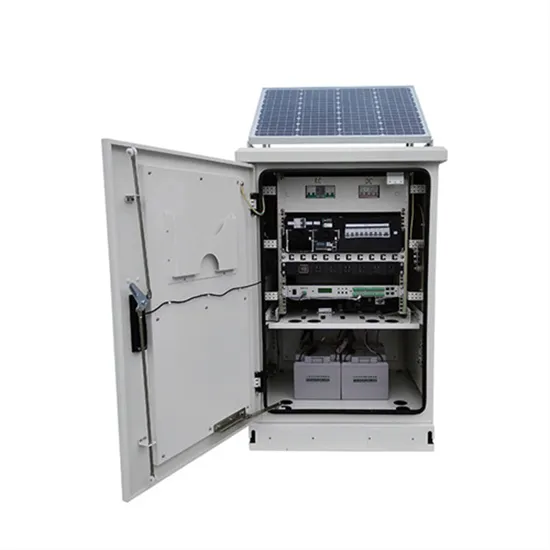
mand, hydro generator available capacity & PV generation capacity and shall manage the system accordingly. A conceptual schematic block diagram for the proposed Solar PV + BESS system with a provision for future synchronization with hydro plants is presented in figure 2 below. Figure 2: Conceptual schematic block diagram of proposed systems
Schematic diagram of BESS control system (Alhejaj and Gonzalez-Longatt, 2016). There are five submodels of this control unit. These are the battery model, the power converter model, the charge controller model, the PQ controller model and the frequency controller model. In addition to these models, three measurement devices are required to be
Power Conditioning System Batteries used in BESS applications can vary in power capacities from tens of kilowatts up to multi-megawatts. However, in a standard utility application, a typical size that Simplified single-line diagram for BESS. Figure 2. 2 MW BESS Power Conversion System enclosure. Technical Datasheet | 2 MW PCS Unit for BESS
The system layout is shown in Figure 3 and consists of the PV panel, two DC/DC converters, one AC/DC converter, the battery energy storage system, the electrical load of the household and the grid
Electrical Reliability Services'' NETA certified technicians, engineers, and project managers are well-versed on the components that make up your Battery Energy Storage System (BESS). It''s important to work with an electrical testing company that understands the complexities of your entire power system, to ensure your BESS is installed and
Download scientific diagram | Generic model of Battery Energy Storage System (BESS) in the grid from publication: Reliability Aspects of Battery Energy Storage in the Power Grid | This paper gives
This article is the second in a two-part series on BESS – Battery energy Storage Systems. Part 1 dealt with the historical origins of battery energy storage in industry use, the technology and system principles behind modern BESS, the applications and use cases for such systems in industry, and presented some important factors to consider at the FEED stage of

operation of the BESS equipment. The system will provide automatic operation, remote operation, and dispatch of the BESS equipment from local HMI and web portal. All modes of operation and associated setpoints can be remotely adjustable. Interfaces will allow changes in settings and control modes and will provide access to necessary BESS system
Key performance Indicators of BESS system •Power –maximum continuous power, peak power •Energy –Actual energy capacity, installed capacity, deep discharge High level single line diagram of BESS interconnection and substation 8. BESS lifetime required by Employer 9. General location in country/region 10. Reference site conditions
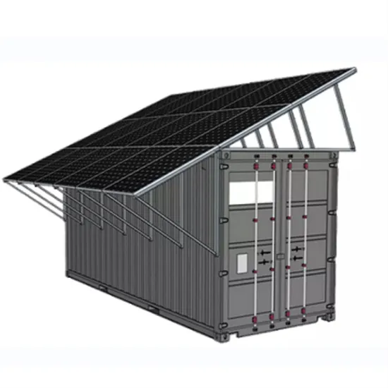
The below image shows a line diagram of a popular type of BESS + Solar system: Battery Thermal Management System (BTMS) – BESS operating without thermal management in high temperatures can lead to lower
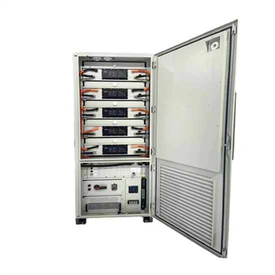
In each BESS there is a specific power electronic level, called PCS (power conversion system) usually grouped in a conversion unit, including all the auxiliary services needed for the proper monitoring. The next level is for monitoring and control of the system and of the energy flow (energy management system).
A BESS is composed of different “levels” both logical and physical. Each specific physical component requires a dedicated control system. Below is a summary of these main levels:
BESS Design and Engineering These are the FEED and detailed design considerations that must be made when deciding on how best to integrate BESS into a design. The grid connection point should be decided early in the design phase. It may be decided to split the BESS into two or more distinct units for connection at multiple points in the network.
The type of connection should be decided early. If the BESS shall connect to a LV or MV connection point. Most battery systems will not exceed 1500 V DC, as this would bring them into the HV classification range and entail increased equipment and operational demands.