Download scientific diagram | Circuit schematic of flyback PV inverter power stage based on two interleaved cells from publication: An interleaved flyback inverter for residential photovoltaic
A voluntary solar power supply circuit and a transformer may be added within to charge the battery when necessary (check diagram). Solar Inverter Circuit Diagram: To understand well how to construct a solar inverter,
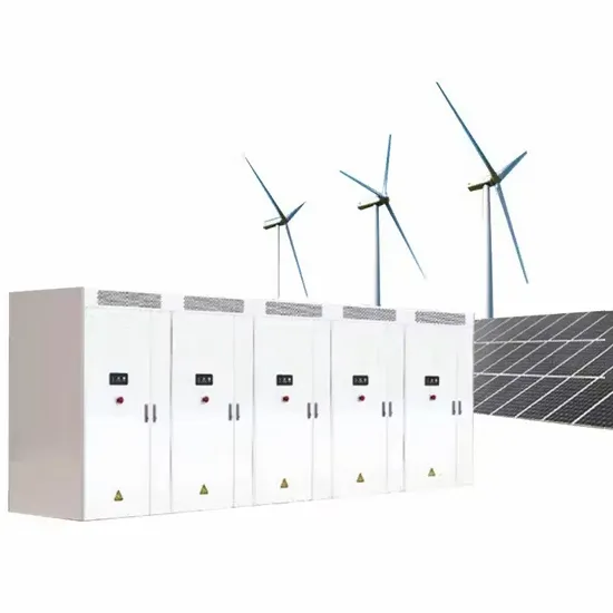
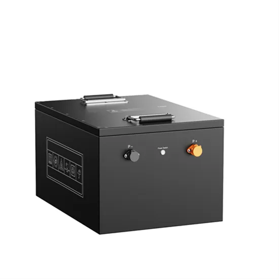
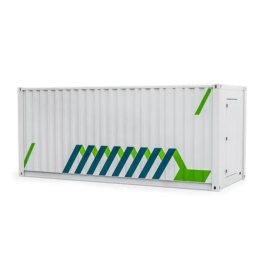
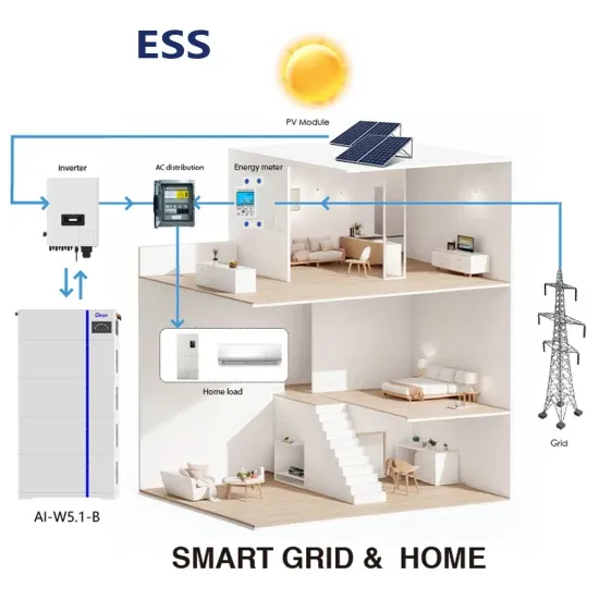
Photovoltaic system diagram: components. A photovoltaic system is characterized by various fundamental elements:. photovoltaic generator; inverter; electrical switchpanels; accumulators. Photovoltaic

Fig. 6 Control diagram of the PV energy conversion system The simulation model of the PV inverter Control structure was built based on a graphical intuitive way as it can be seen from
3 天之前· Figure 3 represents the schematic of photovoltaic 5-level quasi Z-source inverter. It has two PV sources that act as separate input to the H-Bridges. The PV panels are followed by
View a complete reference design of this system simulation and rapid prototyping and see a demonstration of a real-time simulation of a 3-phase single-level inverter with RLC filter and load. The real-time HIL
rid-Tie Solar Inverter System . 1.3. PV Panel Electrical Characteristics . Solar inverter power output varies almost directly with sunlight, but current drops off much faster until you reach

of the inverter can achieve photovoltaic grid-connected, so that solar energy can be fully utilized. 2. System Block Diagram of Photovoltaic Grid-Connected Inverter Fig.1 shows the overall
The simulation results show that the designed buck and boost converters can be used to replace transformers from conventional inverter circuit to make low-THD, highly efficient and cost
way of photovoltaic voltage control for achieving MPP. So, in algorithm implementation using Mat lab/Simulink, it is essential to control and change only d and not the actual duty cycle, D.The
This paper deals with design and simulation of a three phase inverter in MATLAB SIMULINK environment which can be a part of photovoltaic grid connected systems. The converter used is a Voltage Source Inverter (VSI) which is controlled using synchronous d-q reference frame to inject a controlled current into the grid. Phase lock loop (PLL)
Photovoltaic (PV) module integrated with advanced inverter technologies has the ability to indirectly tune the reactive power from the grid with strict precision which is impossible to achieve with conventional passive compensators.
With PV*SOL you can deisgn and simulate all types of modern PV systems. From the small rooftop system with a few modules to medium-sized systems on commercial roofs to solar parks with up to 100,000 modules - PV*SOL supports you with numerous tools for design and simulation. Choose the type of design that best suits you and your PV project!
Abstract-This paper presents the development of inverter simulation model in Grid-Connected Photovoltaic System (GCPV) in Matlab/Simulink software. This work is a part of the development of a complete GCPV system simulation model.
A typical PV grid tied inverter uses a boost stage to boost the voltage from the PV panel such that the inverter can feed current into the grid. The DC bus of the inverter needs to be higher than the maximum grid voltage. Figure 20 illustrates a typical grid tied PV inverter using the macros present on the solar explorer kit. Figure 20.
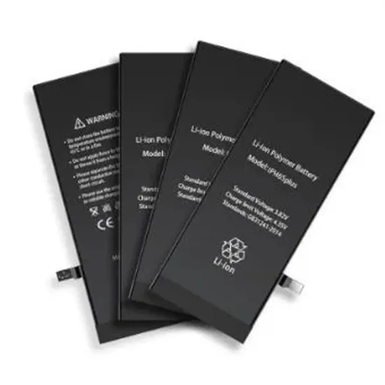
The solar panel or PhotoVoltaic (PV) panel, as it is more commonly called, is a DC source with a non-linear V vs I characteristics. A variety of power topologies are used to condition power from the PV source so that it can be used in variety of applications such as to feed power into the grid (PV inverter) and charge batteries.