A capacitive-coupling grid-connected inverter, consisting of a full-bridge single-phase inverter. A schematic diagram of the islanded microgrid is shown in Figure 12, where, the power line
A grid tie solar system wiring diagram shows the connections between the solar panels, inverter, meter, and utility grid. It also includes safety features such as disconnect switches and surge
Photovoltaic power generation is a vital part of the overall renewable energy scheme. In all solar inverters, the micro solar inverters are critical components. This paper describes how to use a
An on-grid inverter circuit diagram refers to a schematic representation of the electrical components and connections used in a grid-tied inverter system. This type of inverter is designed to convert direct current (DC) power, typically
Grid Tie Inverter: This is a meaty project so buckle up! Grid tie inverters enable you to push power into a mains socket which is an awesome ability. I find the power electronics and control systems involved in their design interesting so I

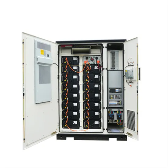
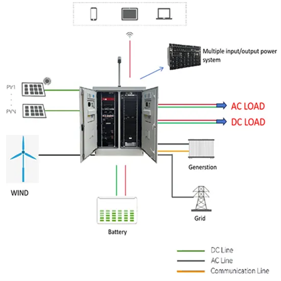
components, solar inverter units, energy storage unit, and electricity load and so on. Figure 2. O. ff-Grid Solar Inverter System . While the grid-tie solar inverter system is mainly used in parallel
The microgrid shown in Figure 6 will initially be used to illustrate the dynamic behaviour of the inverter control scheme. Inverter-based sources are located at buses 2 and 3, and a constant power load is connected to bus 4. Bus 1 forms the interface between the microgrid and the rest of the power system, which is modeled as an infinite bus.
The inverter interface with the microgrid can be modeled according to Pgen= ViVt X sin(it) (10) whereVi\iis the voltage synthesized at the inverter bus, Vt\tis the voltage on the grid side of the filter, andjXis the effective impedance between those two points. Assuming
Microgrid (MG) can improve the quality, reliability, stability and security of conventional distribution systems. Inverter based MGs are an appropriate, attractive and functional choice for power distribution systems. Inverters in a MG have multiple topologies that have been referenced in various literature.
The control design of this type of inverter may be challenging as several algorithms are required to run the inverter. This reference design uses the C2000 microcontroller (MCU) family of devices to implement control of a grid connected inverter with output current control.
The paper has proposed an inverter control strategy that allows autonomous microgrids to be supplied solely by inverter-based sources. The inverter controls regulate the power delivered to the grid, the terminal voltage, and also maintain the microgrid frequency.
Background of Microgrids Modeling 3 Microgrids as the main building blocks of smart grids are small scale power systems that facilitate the effective integration of distributed energy resources (DERs). In normal operation, the microgrid is connected to the main grid.